photographs of my designs and creations
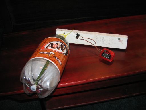
This thing measures how much wire has been wound on one of the electromagnets I make. A soda bottle rotates on an axle, and a flipper made of a yellow cable tie-strap whacks a small microswitch each time the bottle rotates. This steps a slightly-hacked pedometer from the local Dollar Tree store. The whole thing is clamped on a ceiling beam between the reel of wire and my little lathe. The wire is pulled from the reel and is wound once around the soda bottle and then down onto the core to be wound. As wire is pulled from the reel, the bottle rotates, and when we multiply the circumference of the soda bottle by the number of turns shown on the pedometer, we'll know how much wire has been wound onto the core. It works. You could possibly leave off the counter and just count the number of times the yellow flipper clicks as the bottle goes around, but the counter is lots better. To make a pedometer into a counter, pry open the case and solder wires to the terminals of the weighted switch inside. Then jam something into the pivoted weight so it won't move. It takes a bit of patience, especially if your hands are shaky like mine. This was from May of 2006 or so.
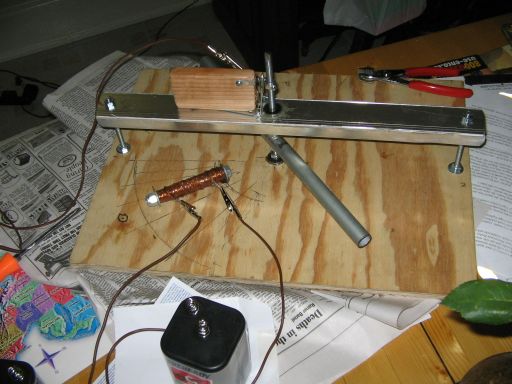
This is a demonstration of electromagnets and motors. At the left is an electromagnet, a coil wound with about 100 feet of #24AWG magnet wire, the core is a 3/8 inch bolt. The wire is not bare: it is coated with clear plastic insulation. The coil was wound on a lathe using the magnet-wire meter shown above. After it was wound, enough 'Five minute' clear epoxy glue was dribbled onto the coils to stabilize and protect them.
The silver bar that's positioned at an angle is a piece of 1/2-inch steel electrical conduit about a foot long. It is pierced by a shaft of 5/16-inch threaded rod, its position maintained by nuts above and below the bar. The shaft is carried in a pair of roller-skate bearings that are held in place with epoxy glue, and the cross-bar that carries the upper bearing is a piece of aluminum extrusion salvaged from a deceased shower stall.
The steel bar--called the 'rotor,' I guess--rotates just above the electromagnet with about 1/8 inch clearance. The magnet is held down to the plywood baseboard with a pair of high-strength button magnets glued to the board. This method of mounting is used so that the electromagnet may easily be removed and demonstrated separately. The bearings assure that the rotor will rotate with very little effort, so that if the electromagnet is energized when one end of the bar is within about 30 degrees the bar will swing over to the electromagnet and then stall directly overhead. Further, if the electromagnet is de-energized just before the bar reaches its stalled position, the bar will continue to swing in the same direction. This is repeated as the other end of the bar swings around. When the magnet is turned on and then off at the appropriate times the bar will begin to rotate around at a fairly respectable rate of speed if we use a good 6V lantern battery.
This is the switch that turns the electromagnet on and off at the appropriate time for the appropriate amount of time. A cam is made by drilling a 9/64-inch (I think) hole entirely through a 5/16-inch nut (of the type which has a nylon insert to keep it locked on its bolt) and tapping it for an 8-32 thread. Two round-head 8-32 machine screws are cut off as short as possible and screwed into either side of the hole. This finished cam is threaded onto the rotor shaft.
The wood block and the strap hinge carry silver-bronze (maybe) contacts that were salvaged from an old electric power relay. It is quite important to use this quality of contact, because the major weakness with earlier versions of this motor was the inadequacy of moving electrical contacts. The steel-to-steel contacts we used in the past can work if designed properly, but they are quite unreliable and the motor eventually stops when oxides build up.
The non-moving leaf of the strap hinge is trapped beneath the wood block, and the fixed relay contact mounted to the block with an 8-32 machine bolt which also acts as an electrical terminal. The moving contact was secured to the moving leaf of the hinge with, guess what, a cut-off 8-32 machine bolt.
The motor clips along with a cheerful clacking, and my wife says that the action is somewhat mesmerizing. The switch (known in the business as the 'commutator,') works in an obvious fashion. There is room for improvement, of course. The wires have a tendency to get in the way of the rotor, so some sort of wire looms are needed. And there is a bit of uncertainty with the current path to the moving contact. The hinge pivot may or may not be a good conductor, or if it is it may not remain a good conductor; this motor uses a _lot_ of current, about five amperes, and thin connecting wires and uncertain contacts will degrade its performance drastically. Ideally there would be a thin piece of wire braid from the moving contact to a terminal mounted on the wood block, but people have a tendency to clip alligator clips anywhere they can and then pull them off, and a wire that's flexible enough to allow the switch to work properly would not survive long. In this case I have jumped the hinge pivot with a wire that is not visible here. It lives between the moving hinge leaf and the wood block.
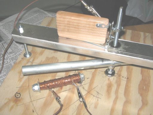
This is a demonstration of electromagnets and motors. At the left is an electromagnet, a coil wound with about 100 feet of #24AWG magnet wire, the core is a 3/8 inch bolt. The wire is not bare: it is coated with clear plastic insulation. The coil was wound on a lathe using the magnet-wire meter shown above. After it was wound, enough 'Five minute' clear epoxy glue was dribbled onto the coils to stabilize and protect them.
The silver bar that's positioned at an angle is a piece of 1/2-inch steel electrical conduit about a foot long. It is pierced by a shaft of 5/16-inch threaded rod, its position maintained by nuts above and below the bar. The shaft is carried in a pair of roller-skate bearings that are held in place with epoxy glue, and the cross-bar that carries the upper bearing is a piece of aluminum extrusion salvaged from a deceased shower stall.
The steel bar--called the 'rotor,' I guess--rotates just above the electromagnet with about 1/8 inch clearance. The magnet is held down to the plywood baseboard with a pair of high-strength button magnets glued to the board. This method of mounting is used so that the electromagnet may easily be removed and demonstrated separately. The bearings assure that the rotor will rotate with very little effort, so that if the electromagnet is energized when one end of the bar is within about 30 degrees the bar will swing over to the electromagnet and then stall directly overhead. Further, if the electromagnet is de-energized just before the bar reaches its stalled position, the bar will continue to swing in the same direction. This is repeated as the other end of the bar swings around. When the magnet is turned on and then off at the appropriate times the bar will begin to rotate around at a fairly respectable rate of speed if we use a good 6V lantern battery.
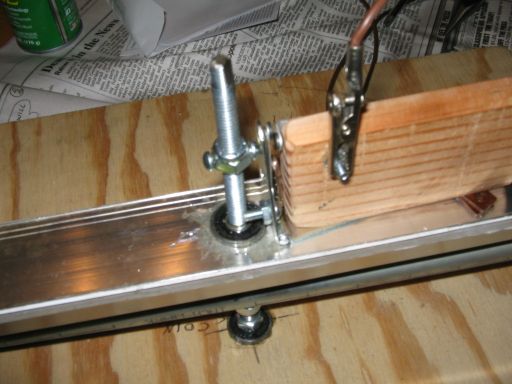
This is the switch that turns the electromagnet on and off at the appropriate time for the appropriate amount of time. A cam is made by drilling a 9/64-inch (I think) hole entirely through a 5/16-inch nut (of the type which has a nylon insert to keep it locked on its bolt) and tapping it for an 8-32 thread. Two round-head 8-32 machine screws are cut off as short as possible and screwed into either side of the hole. This finished cam is threaded onto the rotor shaft.
The wood block and the strap hinge carry silver-bronze (maybe) contacts that were salvaged from an old electric power relay. It is quite important to use this quality of contact, because the major weakness with earlier versions of this motor was the inadequacy of moving electrical contacts. The steel-to-steel contacts we used in the past can work if designed properly, but they are quite unreliable and the motor eventually stops when oxides build up.
The non-moving leaf of the strap hinge is trapped beneath the wood block, and the fixed relay contact mounted to the block with an 8-32 machine bolt which also acts as an electrical terminal. The moving contact was secured to the moving leaf of the hinge with, guess what, a cut-off 8-32 machine bolt.
The motor clips along with a cheerful clacking, and my wife says that the action is somewhat mesmerizing. The switch (known in the business as the 'commutator,') works in an obvious fashion. There is room for improvement, of course. The wires have a tendency to get in the way of the rotor, so some sort of wire looms are needed. And there is a bit of uncertainty with the current path to the moving contact. The hinge pivot may or may not be a good conductor, or if it is it may not remain a good conductor; this motor uses a _lot_ of current, about five amperes, and thin connecting wires and uncertain contacts will degrade its performance drastically. Ideally there would be a thin piece of wire braid from the moving contact to a terminal mounted on the wood block, but people have a tendency to clip alligator clips anywhere they can and then pull them off, and a wire that's flexible enough to allow the switch to work properly would not survive long. In this case I have jumped the hinge pivot with a wire that is not visible here. It lives between the moving hinge leaf and the wood block.
The fans are switched by a crude arm of copper wire topped by a weight made of a bundle of otherwise-useless 50/50 plumber's solder. Pivoted at its base on an 8-32 bolt, it'll swing against one of two crossbars made of the same copper wire, thus completing the power circuit of one fan or the other. The power is supplied by a 12V 300mA wall-transformer type power power supply. The switch is wired such that it connects the power to whichever fan is lower. This makes the higher fan slow down and the lower fan speed up, and the difference in lift makes the whole thing tip over on its cork pivot, which then makes the switch arm flop over to connect the lower fan. It takes about six seconds for each rock, or twelve seconds per cycle, and it is so feeble that it is vital to balance the beam (okay, the pipe) properly.
I tried to improve the thing's looks and operation, but the cork proves to be an almost frictionless pivot and the switch, crude as it is, just keeps on switching. I have added a bit of white tape to the fan hubs to make the relative speeds of the fans more obvious; the fans coast for a long time, so both are always spinning--but at different speeds. The device, which I have decided is best off without a real name right now, has been sitting in a display case at COSI science center in Columbus, Ohio for about two months: it begins rocking when they turn the lights on in the Gadgets section of the museum each morning and seems to attract a good deal of attention. I suppose it illustrates principles of feedback and lift, sort of.